
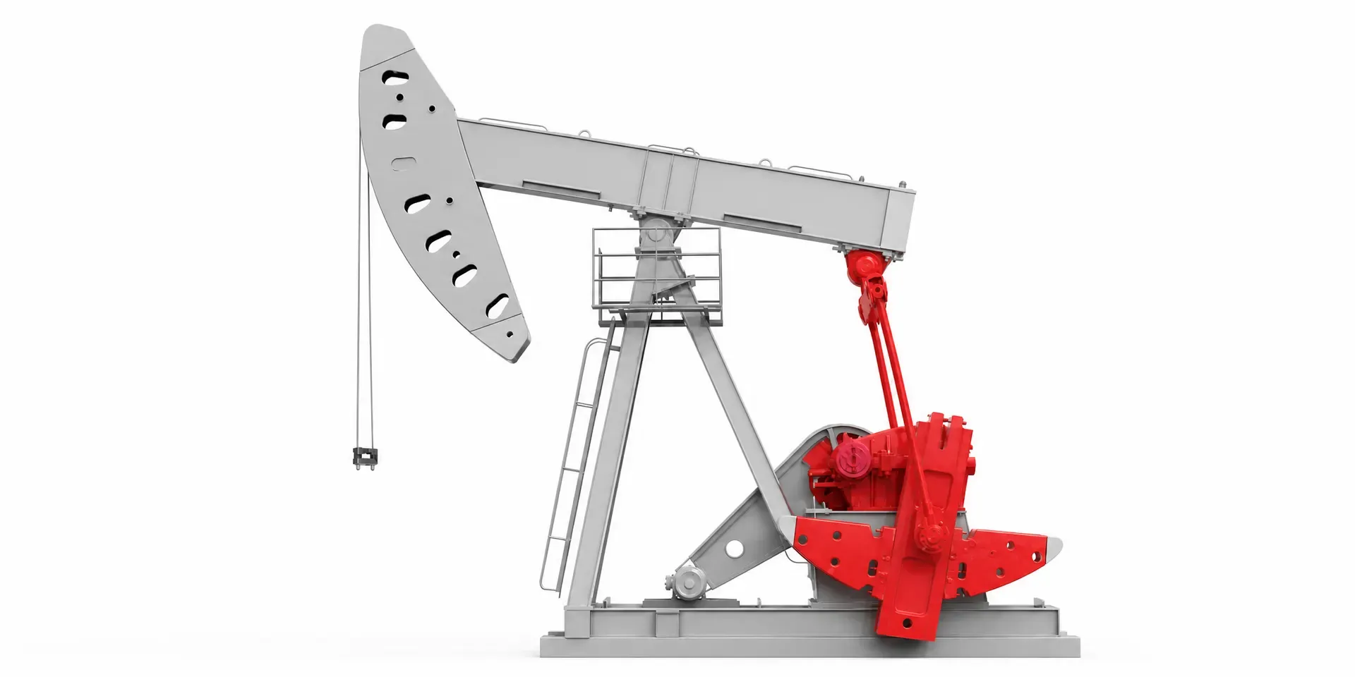
The most common sizing error on a beam pump is not choosing the wrong technology. It is selecting on average power, discovering the motor cannot hold strokes per minute under peak torque, and compensating by fitting something larger — which then runs even further from its efficient operating point.
Step one: calculate the cyclic load, not the nameplate
A beam pump motor does not see steady load. The upstroke lifts the rod string plus the fluid column; the downstroke unloads sharply. Power across one cycle can swing 30–50%. Three numbers set that envelope:
| Parameter | Typical range | What it determines |
|---|---|---|
| Well depth | A few hundred to 10,000+ ft | Rod string weight, and therefore peak torque |
| Strokes per minute | 4–12 for conventional units, lower for long-stroke designs | Rated speed and start/stop frequency |
| Polished rod load | Set by the unit designation (e.g. C-228D-213-86) | Gearbox input torque, and back-calculated motor power |
Peak torque capability and overload margin are the specifications that matter here. Rated power alone does not describe whether a motor can carry the top of the stroke.
Step two: belt-driven induction, or direct-coupled permanent magnet
This is the decision with the largest consequences. The conventional arrangement is an induction motor driving through belts into a gear reducer. The alternative couples a permanent-magnet synchronous motor to the gearbox input shaft and deletes the belt drive entirely.
| Induction + belt drive | PM semi-direct drive | |
|---|---|---|
| Transmission losses | Belt slip and wear | No belt stage |
| Wear parts | Belts and motor bearings on a replacement cycle | Belt and motor-bearing wear removed |
| Gearbox loading | Sheave radial load carried by gearbox bearings | Improved input shaft loading |
| Speed adjustment | Change sheaves, or add a VFD | Continuously variable strokes per minute |
| Verified savings | Baseline | 21–76%, project dependent |
| Best fit | Budget-led, standardised conventional wells | Energy ROI, or wells with a history of gearbox failures |
The width of that savings range is the honest part of the answer. Field results at the top of the range came from installations where the existing belt drive had degraded substantially; results near the bottom came from equipment already in good condition. Quoting a single figure to a customer before surveying their equipment is how commitments get made that cannot be met.
Note: the underlying project data is LEADGO’s own measured results. Customer identification has been withheld pending release approval.
Step three: verify site conditions before ordering
The first two steps fix the drive topology and product series. The third decides whether the motor can actually be installed and reach design life.
- Supply voltage. North American NEMA sites commonly run 460 V or 575 V; IEC markets run 380 V or 660 V. The standard catalogue rating is 380 V, so North American orders need the voltage variant confirmed explicitly.
- Ingress protection. IP55 is the standard rating. Sites with heavy dust or salt exposure — Middle East, coastal installations — should be specified to IP65.
- Difficult starting duty. Heavy oil and deep wells with high breakaway torque may be better served by a high-slip, high-starting-torque induction design than by permanent-magnet direct drive. Not every well is a direct-drive candidate.
- Progressive cavity pumps are a different problem. If the well runs a PC pump rather than a beam pump, the selection logic changes completely: a flameproof vertical hollow-shaft permanent-magnet motor drives it directly. One documented field project recorded 27.96% energy savings on that configuration.
Getting the order right
Steps two and three are frequently done well. Step one is frequently skipped, because a power table is faster than a load calculation. That shortcut is the source of most of the oversized motors in the field — and an oversized motor on a cyclic load gives away exactly the efficiency the upgrade was supposed to capture.
Related: Permanent magnet vs induction motors in oilfield duty.