
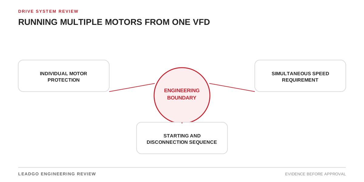
A common drive is suitable only when every motor remains protected through all switching states. Project teams should be able to reproduce the decision without relying on memory or an email fragment; the multi-motor VFD system record must identify this boundary explicitly.
Define what the review must prove — multi-motor VFD system
A variable-frequency drive changes voltage waveform, motor heating, bearing-current exposure, speed range and control behaviour; the multi-motor VFD system record must identify this boundary explicitly. Review settings and hardware as one drive system, with the actual cable, load and operating range included; the multi-motor VFD system record must identify this boundary explicitly.
Fix the review point in time: proposal, approved design, factory test, installation or operating condition; the multi-motor VFD system record must identify this boundary explicitly. A value can be correct in one state and misleading in another; the multi-motor VFD system record must identify this boundary explicitly.
The evidence chain — multi-motor VFD system
| Step | Review point | What to confirm |
|---|---|---|
| 1 | Individual motor protection | Record individual motor protection with its source, revision and responsible reviewer. |
| 2 | Simultaneous speed requirement | Define simultaneous speed requirement and identify the controlled document or measurement that supports it. |
| 3 | Starting and disconnection sequence | Confirm starting and disconnection sequence under the stated operating condition rather than a nominal assumption. |
Compare the inputs on one common basis. Mixing a rated value, a temporary site reading and a worst-case calculation can produce a neat answer that does not describe a real condition; the multi-motor VFD system record must identify this boundary explicitly.
What a checklist can miss — multi-motor VFD system
- Borrowing an unverified input. Using individual motor protection from a similar motor or site. Small differences in supply, mounting, load or environment can change the result; the multi-motor VFD system record must identify this boundary explicitly.
- Treating an interface as a late detail. Closing the review before starting and disconnection sequence is documented. Approval should show the open action instead of burying it in a general note; the multi-motor VFD system record must identify this boundary explicitly.
Where the evidence is incomplete, define what must be supplied and who owns it; the multi-motor VFD system record must identify this boundary explicitly. The review can remain provisional without pretending the boundary is settled.
What belongs in the closeout record — multi-motor VFD system
Keep these items with the approval or maintenance record:
- source and operating condition for individual motor protection
- dated evidence for simultaneous speed requirement
- approved limit or disposition for starting and disconnection sequence
Keep the evidence with the equipment identity and operating case. A standalone screenshot or number is difficult to audit once the project team and site condition change; the multi-motor VFD system record must identify this boundary explicitly.
Decision rule — multi-motor VFD system
A common drive is suitable only when every motor remains protected through all switching states. The decision is complete when the stated inputs refer to the same equipment, revision and operating case; the multi-motor VFD system record must identify this boundary explicitly. Otherwise record the gap and its owner.
Going deeper — multi-motor VFD system
Build an operating-state protection matrix — multi-motor VFD system
The design must be checked in states, not only at the maximum combined load. List every permitted combination and prove that the drive and each branch remain protected.
| State | Motors connected | Required check | Evidence for release |
|---|---|---|---|
| Normal all-running | All intended motors | Sum of steady currents, drive loading, common speed suitability and branch heating | Measured or calculated loading at the stated process condition |
| One motor stopped but connected | Mixed running/stopped | Whether a stopped motor can overheat, rotate unexpectedly or see unsuitable voltage | Control narrative and individual protective function test |
| One branch isolated | Reduced group | Drive identification/control stability and remaining motor current sharing | Approved minimum-group test or supplier confirmation |
| Sequential start | Motors added in steps | Current-limit interaction, acceleration time and process transient | Trend of current, speed and branch status for each step |
| Trip of one motor | Faulted branch opens or remains connected | Selectivity, safe isolation and effect on remaining motors | Protection test and defined restart logic |
| Maintenance mode | One branch locked out | Prevention of unintended energisation from common output | Isolation procedure, interlock test and warning labels |
A single overload value in the drive cannot normally represent the thermal condition of several unequal motors. The solution may require individual electronic protection, thermistors or RTDs, branch contactors and coordinated fault protection. The exact arrangement must follow the suppliers’ permitted topology and applicable electrical rules.
Size the system from real combinations — multi-motor VFD system
Collect rated current, duty basis, efficiency, power factor, speed range, cooling method and load torque for every motor. Confirm whether the motors are identical. A common frequency command gives a common electrical frequency, not equal mechanical load sharing. Fans, pumps and conveyors can have different curves even when nameplates match.
Check the drive for combined continuous current, short-time overload during the worst allowed acceleration, switching-frequency derating, ambient/altitude derating and input requirements. Do not size solely by adding motor kilowatts. Current and overload duty govern many drive decisions.
Cable length must be considered as a system total and by branch. Reflected-wave stress, filters and output-reactor location need supplier review. If an output filter is proposed, confirm it remains suitable across the group current and all allowed connected combinations.
Switching and restart decisions — multi-motor VFD system
Opening a contactor on a live VFD output can damage equipment or create uncontrolled transients unless the drive manufacturer explicitly supports the sequence. Define when output switching is allowed, how the drive proves disabled output, and how contactor feedback is interlocked.
Adding a spinning motor to an energised common bus is a separate problem. The control system may need coast-to-stop, flying-start capability or a prohibited-state interlock. Record the worst residual speed and direction. Do not assume a rotating load will synchronise harmlessly.
After a power interruption, determine whether all motors restart together, in sequence, or remain stopped. Consider process consequences: simultaneous fan restart may be acceptable while simultaneous loaded conveyor restart may exceed drive current or mechanical capacity.
Applicability boundary — multi-motor VFD system
One VFD can be practical where motors intentionally operate at the same commanded speed, the process tolerates common control, and each branch receives adequate protection. It is usually a poor fit where motors need independent speeds, frequent independent switching, different minimum cooling speeds or tightly controlled torque sharing.
This article is not a wiring design. Grounding, short-circuit protection, branch isolation and safety functions require project-specific engineering. In hazardous locations, switching equipment, motor protection and thermal behaviour must also satisfy the applicable certification and installation conditions.
Common design errors — multi-motor VFD system
- Assuming identical nameplates guarantee equal load.
- Omitting branch protection because the drive has an overload function.
- Running a smaller motor below its safe cooling speed while the larger motor sets the process requirement.
- Allowing operators to connect or disconnect motors without a drive-state interlock.
- Autotuning a group as though it were one motor without supplier approval.
- Ignoring the minimum connected group when selecting an output filter or control mode.
Supplier data and acceptance record — multi-motor VFD system
Ask the drive supplier for approved multi-motor topology, maximum combined cable conditions, supported output switching, permitted control modes, current-limit behaviour and filter requirements. Ask each motor supplier for VFD suitability, thermal protection, minimum speed, insulation constraints and permissible switching duty. Ask the process supplier for every operating combination, torque-speed curves and restart sequence.
Commissioning should test the defined states with branch status, drive current, individual motor current, speed and protection indications recorded. The final matrix must show which states passed, which are prohibited and which depend on an operating restriction. That is a far stronger handover than a successful all-motors-running demonstration.